


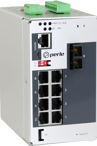
Perle IDS-409G
Managed Industrial Ethernet Switch with Gigabit Fiber
9 port Compact DIN Rail Switch
 Properties
 Description
 Further Information
 Similar products
 Print this page
 Request Price
 show my notes
 PDF
PDF
 Properties
 Description
 Further Information
 PDF
PDF
- 10/100/1000Base-T ( RJ45 ) ports for Gigabit and Fast Ethernet devices
- 1000Base-X SC/ST fiber ports
- IP Manageability, VLAN and resiliency management
- Digital inputs for generation of alerts
- Compact, corrosion resistant case attaches to a standard DIN Rail
- Redundant dual power input 12/24/48 VDC, 24 VAC
- Out-of-band management via RJ45 or USB serial ports
- Programmable Controller safety and Hazardous Location Certification
- -40 to 75C industrial operating temperature ( XT Models )
Choose any combination of 10/100/1000-Base-T Ethernet copper ports and 1000Base-X fiber ports to meet the needs of your environment.
8 copper, 1 fixed SC/ST fiber port
7 copper, 2 fixed SC/ST fiber ports
6 copper, 3 fixed SC/ST fiber ports
Utilizing fiber is critical in environments, like industrial plants, where high levels of electromagnetic interference ( EMI ) is a common phenomenon.
This interference can cause data corruption over copper-based Ethernet links.
However, data transmitted over fiber optic cable is completely immune to this type of noise ensuring optimal data transmission across the plant floor.
Perle Industrial-grade Ethernet Switches are designed to stand up to extreme temperatures, surges, vibrations, and shocks found in industrial automation, government, military, oil and gas, mining and outdoor applications.
Perles Fast Setup feature provides simple Plug and Play installation to get your Ethernet devices networked immediately.
engineers.
Simple Plug and Play installation to get your Ethernet devices networked immediately is available with Perles Fast Setup feature.
The familiar Command Line Interface ( CLI ), via in-band Telnet or the out-band serial console port, will be appreciated by CCNA ( Cisco Certified Network Associate ) and CCNP ( Cisco Certified Network Professional ) trained
CCNA ( Cisco Certified Network Associate ) and CCNP ( Cisco Certified Network Professional ) trained engineers will appreciate the familiar Command Line Interface ( CLI ) via in-band Telnet or the out-band serial console port.
P-Ring, management VLAN, QoS, RMON, N:1 port mirroring and local alert log, are only a few of the comprehensive management functions supported in the IDS-409G.
In addition, the switch can be managed with an IPv6 address.
These rugged fan-less switches that are hardened to provide superior reliability in -10 to 60°C.
In addition, every component on every industrial (XT) model has been designed and tested to handle operating temperatures between -40 and 75C.
Simple deployment
- Zero-touch discovery using Dynamic Host Control Protocol (DHCP), Perles "Fast Setup"
for first time installation, provides simple deployment in Ethernet environments
Resiliency
- STP and RSTP protocols for fast recovery.
- Perles P-Ring protocol for fastconvergence in ring topologies
- Link Standby is a link recovery feature for two links that provides a simple alternative to spanning tree protocols for link redundancy
Managebility
- Web Device Manager, Telnet, SNMP and Perles PerleView NMS for centralized management
- In-band management via RJ45 or USB serial ports
- Use an IPv4 or IPv6 address
- Removable MicroSD flash for conifuration files and firmware backup and restoration
Rugged design for harsh environments
- Corrosion resistant case
- Programmable Controller Safety certified
- Certified for hazardous locations
- Extended industrial temperature models
Reliable operation
- Fan-less, no moving parts
- Dual power input. Connect to separate power sources for redundancy.
- Reverse polarity protection
- Overload current protection
- Handles vibration and shock conditions found in industrial environments
Real-time Ethernet performance
- Fast wire-speed , store and forward switching
- Auto-sensing for speed and duplex
- Auto-mdi/mdix-crossover works with straight and crossover cables
Features
| Performance Features | |
|---|---|
| Port Auto-sensing | Auto-sensing of port speed and auto-negotiation of duplex on all switch ports for optimizing bandwidth |
| Auto MDI/MDIX | Medium-dependent interface crossover ( Auto-MDIX ) capability on 10/100 and 10/100/1000 mbps interfaces that enables the interface to automatically detect the required cable type ( straight thru or crossover ) and to configure the connection appropriately |
| 802.3x flow control | IEEE 802.3x flow control on all ports. ( The switch does not initiate pause frames ) |
| Storm Control | Storm control prevents traffic on a LAN from being disrupted by a broadcast, multicast, or unicast storm on one of the physical interfaces. A LAN storm occurs when packets flood the LAN, creating excessive traffic and degrading network performance. Storm Control enables limits to be placed on broadcast, multicast and unicast traffic |
| Static MAC Addressing | This feature enables the manual configuration of the MAC addresses on a per port basis. Flooding is prevented by retaining MAC entries across a reboot of the switch. |
| Port Blocking | Port Blocking provides the ability to block the flooding of unknown layer 2 unicast and multicast traffic on an Interface |
| IPV4 IGMP Snooping | Internet Group Management Protocol ( IGMP ) constrains the flooding of multicast traffic by dynamically configuring Layer 2 interfaces so that multicast traffic is forwarded to only those interfaces associated with IP multicast devices. IGMPv1, v2, v3, IGMP snooping querier mode, IGMP report suppression, topology change notification and robustness variable features are supported |
| Port Quick Disconnect | In some network environments, it is desirable to move an Ethernet from one switch port to another and have the device come on-line quickly. The Port Quick Disconnect feature if enabled, provides an immediate age-out of the MAC addresses learned on the port when the port status changes from a link-up to a link-down state |
| Manageability Features | |
| Web Device Manager | The Perle Web Device Manager is an embedded Web based application that provides an easy to use browser interface for managing the switch. Unlike competitive products, Java applet technology is not required or used |
| Command Line Interface ( CLI ) | A familiar text-based Command Line Interface that is based on accepted industry standard syntax and structure. Ideal for CCNA and CCNP trained engineers, this interface is available via in-band Telnet or the out-band serial console port |
| SNMP | Manage the switch with an snmp compatible management station that is running platforms such as HP Openview or Perles PerleVIEW NMS. SNMP V1 and V2C |
| PerleVIEW | PerleVIEW is Perles SNMP-based network management system that provides a view of the network with a large scale of Perle networking devices. |
| IPv6 | Manage with an IPv4 or IPV6 address |
| DHCP Client Auto-Configuration | Automates configuration of switch information such as IP address, default gateway, hostname and Domain Name System ( DNS ) as well as TFTP server names. Firmware and configuration file locations are provided through options 54, 66, 67, 125 and 150 |
| DHCP Relay | DHCP Relay is used for forwarding requests from DHCP clients when they are not on the same physical subnet. As a DHCP relay agent the switch operates as a Layer 3 device that forwards DHCP packets between clients and servers. |
| DHCP Option 82 Insertion | Normally used in metro or large enterprise deployments DHCP Option 82 insertion is used to provide additional information on physical attachment of the client. As per RFC 3046, option 82 enables additional pre-defined information to be inserted into the DHCP request packet ( for DHCP Servers that support this option ) |
| LLDP | LLDP-Link Layer Discovery Protocol as per IEEE 802.1AB is a neighbor discovery protocol that is used for network devices to advertise information about themselves to other devices on the network. This protocol runs over the data-link layer, which allows two systems running different network layer protocols to learn about each other ( via TLVs Type-Length-Value ) |
| File Download | Firmware can be transferred via TFTP, HTTP or via insertion of a microSD card. Text-based files that can be created or edited by common text editors. |
| Availability and Redundancy Features | |
| Spanning Tree Protocol ( STP ) | IEEE 802.1D now incorporated in IEEE 802.1Q-2014, STP prevents bridge loops and the broadcast radiation that results from them. |
| Rapid Spanning Tree Protocol ( RSTP ) | Interoperable with STP, RSTP ( IEEE 802.1w ) takes advantage of point-to-point wiring and provides rapid convergence of the spanning tree. Reconfiguration of the spanning tree can occur in less than 1 second |
| P-Ring | P-Ring provides an easy to use method for configuring a ring network using standard spanning tree protocols. Prevents a switch loop scenario in a ring topology. |
| Link Standby | A link recovery feature using a primary and backup link. Provides a simple alternative to spanning tree protocols for link redundancy |
| VLAN Features | |
| VLAN Range | Up to 256 VLANS across a VLAN ID range of 1 to 4000 |
| VLAN Interfaces | Perle switches provide the ability to configure management VLAN interfaces. This enables network administrators to access the switchs management interface from separate VLAN networks |
| Quality of Service ( QoS ) and Class of Service ( CoS ) Features | |
| Classification | IP ToS/DSCP and IEEE 802.1p CoS |
| Congestion Avoidance | Weighted Fair Queuing or Strict Queuing |
| Egress Queues and scheduling |
|
| Monitoring Features | |
| Port Mirroring | N:1 Port Mirroring is a method of monitoring network traffic. With port mirroring enabled, the switch sends a copy of one or more ports to a predefined destination port. Selection of Transmit, Receive frames or both can be made |
| RMON | RMON statistics provided for statistics, history, alarms and events for network monitoring and traffic analysis |
| Syslog | Facility for logging systems messages to an external SYSLOG server |
| Alert Log | Facility for logging systems messages locally |
| Traceroute | Layer 2 traceroute to identify the path that a frame takes from source to destination |
| Power Supply Monitoring | Provides the status of power supplies of the switch |
| Alarm Processing | The switch can monitor global switch conditions as well as individual ports. These alarms can be configured to send messages to ;
|
| Alarm Relay | When enabled, energizes the built-alarm relay triggering an external alarm circuit such as a bell, light or other signaling device according to alarm conditions set |
| Management and Standards | |
| IEEE Standards | IEEE 802.3 for 10Base-T IEEE 802.3u for 100Base-T(X) and 100Base-X IEEE 802.3ab for 1000Base-T EEE 802.3z for 1000BaseX IEEE 802.3x for Flow Control IEEE 802.1D-2004 for Spanning Tree Protocol IEEE 802.1w for Rapid STP IEEE 802.1Q for VLAN Tagging IEEE 802.1p for Class of Service IEEE 802.3ad for Port Trunk with LACP IEEE 802.1AB LLDP |
| SNMP MIB Objects | IEEE8021-PAE-MIB NTPv4-MIB IEEE8021-SPANNING-TREE-MIB SYSAPPL-MIB LLDP-EXT-MED-MIB SNMP-COMMUNITY-MIB LLDP-EXT-MED-MIB IGMP-STD-MIB IEEE8021-MSTP-MIB Q-BRIDGE-MIB LLDP-EXT-DOT3-MIB IF-MIB RSTP-MIB DIFFSERV-DSCP-TC LLDP-EXT-DOT1-MIB IEEE8021-TC-MIB LLDP-MIB RMON2-MIB ENTITY-MIB P-BRIDGE-MIB PERLE-LOGIN-MIB PERLE-ALERT-MIB PERLE-IP-SSH-MIB PERLE-IP-PROTOCOLS-MIB PERLE-USER-MIB PERLE-SMI PERLE-MAC-NOTIFICATION-MIB PERLE-SYSINFO-MIB PERLE-LINKSTANDBY-MIB PERLE-AAA-MIB perle-AAA.MIB PERLE-IPV6-MIB PERLE-LOGGING-MIB PERLE-VLAN-MIB PERLE-IF-MIB PERLE-ENTITY-VENDORTYPE-OID-MIB PERLE-ERR-DISABLE-MIB PERLE-SWITCH-PLATFORM-MIB PERLE-ENVMON-MIB PERLE-TIME-MIB PERLE-PTP-MIB PERLE-P-RING-MIB PERLE-SNMP-MIB PERLE-FILE-TRANSFER-MIB PERLE-SWITCH-GLOBAL-MIB PERLE-BOOT-MIB PERLE-PRODUCTS-MIB PERLE-BANDWIDTH-CONTROL-MIB PERLE-IP-TELNET-MIB PERLE-GVRP-MIB PERLE-PORT-SECURITY-MIB PERLE-DHCP-SERVER-MIB PERLE-GARP-MIB PERLE-ARCHIVE-MIB PERLE-NTP-MIB PERLE-SSL-MIB PERLE-IGMP-MIB PERLE-ACL-MIB PERLE-POE-MIB PERLE-RELOAD-MIB PERLE-ENTITY-ALARM-MIB PERLE-IPV6-NEIGHBOR-MIB PERLE-DOT1X-AUTH-MIB PERLE-TC PERLE-DHCP-CLIENT-MIB PERLE-LINE-MIB PERLE-ARP-MIB PERLE-GMRP-MIB PERLE-MLD-MIB PERLE-IP-HTTP-MIB PERLE-PORT-MONITOR-MIB PERLE-SpTreeExtensions-MIB PERLE-IP-MIB |
Hardware Specs
| Power | ||||||||||||||||||||||||||||||||||||||||||||||||||||||||||||||||||||||||||||||||||||||||||||||||||||||||||||||||||||||||||||||||||||||||||||||||||||||||||||||||||||||||||||||
|---|---|---|---|---|---|---|---|---|---|---|---|---|---|---|---|---|---|---|---|---|---|---|---|---|---|---|---|---|---|---|---|---|---|---|---|---|---|---|---|---|---|---|---|---|---|---|---|---|---|---|---|---|---|---|---|---|---|---|---|---|---|---|---|---|---|---|---|---|---|---|---|---|---|---|---|---|---|---|---|---|---|---|---|---|---|---|---|---|---|---|---|---|---|---|---|---|---|---|---|---|---|---|---|---|---|---|---|---|---|---|---|---|---|---|---|---|---|---|---|---|---|---|---|---|---|---|---|---|---|---|---|---|---|---|---|---|---|---|---|---|---|---|---|---|---|---|---|---|---|---|---|---|---|---|---|---|---|---|---|---|---|---|---|---|---|---|---|---|---|---|---|---|---|---|
| Dual Power Input | Both inputs draw power simultaneously. If one power source fails, the other live source can, acting as a backup, supply enough power to meet the operational needs of the switch. 12/24/48 VDC Nominal. ( 9.6 to 60 VDC) 24 VAC Nominal ( 18 to 30 VAC ) | |||||||||||||||||||||||||||||||||||||||||||||||||||||||||||||||||||||||||||||||||||||||||||||||||||||||||||||||||||||||||||||||||||||||||||||||||||||||||||||||||||||||||||||
| Power Connector | 4-Pin Removable Terminal Block. Grounding screw on metal chassis | |||||||||||||||||||||||||||||||||||||||||||||||||||||||||||||||||||||||||||||||||||||||||||||||||||||||||||||||||||||||||||||||||||||||||||||||||||||||||||||||||||||||||||||
| Maximum Current Consumption @24 vDC | 1 Fiber port = 0.73 amps 2 Fiber ports = 0.69 amps 3 Fiber ports = 0.66 amps | |||||||||||||||||||||||||||||||||||||||||||||||||||||||||||||||||||||||||||||||||||||||||||||||||||||||||||||||||||||||||||||||||||||||||||||||||||||||||||||||||||||||||||||
| Maximum Power Consumption @24 vDC | 1 Fiber port = 17.5 watts 2 Fiber ports = 16.6 watts 3 Fiber ports = 15.7 watts | |||||||||||||||||||||||||||||||||||||||||||||||||||||||||||||||||||||||||||||||||||||||||||||||||||||||||||||||||||||||||||||||||||||||||||||||||||||||||||||||||||||||||||||
| Overload Current Protection | Fused overload current protection | |||||||||||||||||||||||||||||||||||||||||||||||||||||||||||||||||||||||||||||||||||||||||||||||||||||||||||||||||||||||||||||||||||||||||||||||||||||||||||||||||||||||||||||
| Reverse polarity protection | The positive and negative inputs can be reversed providing safe and simple power connectivity. | |||||||||||||||||||||||||||||||||||||||||||||||||||||||||||||||||||||||||||||||||||||||||||||||||||||||||||||||||||||||||||||||||||||||||||||||||||||||||||||||||||||||||||||
| Access Ports | ||||||||||||||||||||||||||||||||||||||||||||||||||||||||||||||||||||||||||||||||||||||||||||||||||||||||||||||||||||||||||||||||||||||||||||||||||||||||||||||||||||||||||||||
| RJ45 | 6,7 or 8 shielded RJ45 ports for 10/100/1000Base-T up to 100 meters ( 328 ft ) Auto-negotiation Auto-MDI/MDIX-crossover for use with either crossover over straight-through cable types Ethernet isolation 1500 V | |||||||||||||||||||||||||||||||||||||||||||||||||||||||||||||||||||||||||||||||||||||||||||||||||||||||||||||||||||||||||||||||||||||||||||||||||||||||||||||||||||||||||||||
| RJ45 Serial Console port | RJ45 DTE Optional rolled and straight thru RJ45 cables and DB adapters are available | |||||||||||||||||||||||||||||||||||||||||||||||||||||||||||||||||||||||||||||||||||||||||||||||||||||||||||||||||||||||||||||||||||||||||||||||||||||||||||||||||||||||||||||
| USB Serial Console port | MicroUSB Type B female port for serial console management. Used as an alternative port for out of band management connections | |||||||||||||||||||||||||||||||||||||||||||||||||||||||||||||||||||||||||||||||||||||||||||||||||||||||||||||||||||||||||||||||||||||||||||||||||||||||||||||||||||||||||||||
| Digital Inputs | Two Digital Inputs are provided that can be used for generation of alarms ( SNMP trap, energizing of on-board Alarm Relay,etc ) | |||||||||||||||||||||||||||||||||||||||||||||||||||||||||||||||||||||||||||||||||||||||||||||||||||||||||||||||||||||||||||||||||||||||||||||||||||||||||||||||||||||||||||||
| Gigabit Fiber port | 1, 2 or 3 1000Base-x fiber port models Duplex SC or ST connector
| |||||||||||||||||||||||||||||||||||||||||||||||||||||||||||||||||||||||||||||||||||||||||||||||||||||||||||||||||||||||||||||||||||||||||||||||||||||||||||||||||||||||||||||
Fiber Port Specs
* 1db/km multimode fiber cable ** as per ITU-T G.652 SMF specifications | ||||||||||||||||||||||||||||||||||||||||||||||||||||||||||||||||||||||||||||||||||||||||||||||||||||||||||||||||||||||||||||||||||||||||||||||||||||||||||||||||||||||||||||||
| Alarms | ||||||||||||||||||||||||||||||||||||||||||||||||||||||||||||||||||||||||||||||||||||||||||||||||||||||||||||||||||||||||||||||||||||||||||||||||||||||||||||||||||||||||||||||
| Alarm Relay |
| |||||||||||||||||||||||||||||||||||||||||||||||||||||||||||||||||||||||||||||||||||||||||||||||||||||||||||||||||||||||||||||||||||||||||||||||||||||||||||||||||||||||||||||
| Switch Properties | ||||||||||||||||||||||||||||||||||||||||||||||||||||||||||||||||||||||||||||||||||||||||||||||||||||||||||||||||||||||||||||||||||||||||||||||||||||||||||||||||||||||||||||||
| Standards | IEEE 802.3 for 10Base-T IEEE 802.3u for 100Base-TX and 100Base-FX IEEE 802.3ab for 1000Base-T IEEE 802.3z 1000BASE-X IEEE 802.3x for Flow Control | |||||||||||||||||||||||||||||||||||||||||||||||||||||||||||||||||||||||||||||||||||||||||||||||||||||||||||||||||||||||||||||||||||||||||||||||||||||||||||||||||||||||||||||
| Processing Type | Store and Forward | |||||||||||||||||||||||||||||||||||||||||||||||||||||||||||||||||||||||||||||||||||||||||||||||||||||||||||||||||||||||||||||||||||||||||||||||||||||||||||||||||||||||||||||
| MAC Address Table Size | 8K | |||||||||||||||||||||||||||||||||||||||||||||||||||||||||||||||||||||||||||||||||||||||||||||||||||||||||||||||||||||||||||||||||||||||||||||||||||||||||||||||||||||||||||||
| VLAN ID range | 1 to 4000 | |||||||||||||||||||||||||||||||||||||||||||||||||||||||||||||||||||||||||||||||||||||||||||||||||||||||||||||||||||||||||||||||||||||||||||||||||||||||||||||||||||||||||||||
| IGMP groups | 1024 | |||||||||||||||||||||||||||||||||||||||||||||||||||||||||||||||||||||||||||||||||||||||||||||||||||||||||||||||||||||||||||||||||||||||||||||||||||||||||||||||||||||||||||||
| Packet Buffer Memory | 1 Mbit | |||||||||||||||||||||||||||||||||||||||||||||||||||||||||||||||||||||||||||||||||||||||||||||||||||||||||||||||||||||||||||||||||||||||||||||||||||||||||||||||||||||||||||||
| Indicators | ||||||||||||||||||||||||||||||||||||||||||||||||||||||||||||||||||||||||||||||||||||||||||||||||||||||||||||||||||||||||||||||||||||||||||||||||||||||||||||||||||||||||||||||
| Power | This LED is turned on when the appropriate level of voltage is applied to one or both of the power inputs | |||||||||||||||||||||||||||||||||||||||||||||||||||||||||||||||||||||||||||||||||||||||||||||||||||||||||||||||||||||||||||||||||||||||||||||||||||||||||||||||||||||||||||||
| System | Indicates whether the switch O/S is operating normally | |||||||||||||||||||||||||||||||||||||||||||||||||||||||||||||||||||||||||||||||||||||||||||||||||||||||||||||||||||||||||||||||||||||||||||||||||||||||||||||||||||||||||||||
| RJ45 Ethernet | These integrated colored LEDs indicate link, activity and speed for each port. | |||||||||||||||||||||||||||||||||||||||||||||||||||||||||||||||||||||||||||||||||||||||||||||||||||||||||||||||||||||||||||||||||||||||||||||||||||||||||||||||||||||||||||||
| Fiber Link | Fiber link LED indicates Link and Data Activity | |||||||||||||||||||||||||||||||||||||||||||||||||||||||||||||||||||||||||||||||||||||||||||||||||||||||||||||||||||||||||||||||||||||||||||||||||||||||||||||||||||||||||||||
| Alarm | The alarm LED ( Red ) will be turned on under alarm conditions | |||||||||||||||||||||||||||||||||||||||||||||||||||||||||||||||||||||||||||||||||||||||||||||||||||||||||||||||||||||||||||||||||||||||||||||||||||||||||||||||||||||||||||||
| P-Ring Master LED | Status of the P-Ring Master | |||||||||||||||||||||||||||||||||||||||||||||||||||||||||||||||||||||||||||||||||||||||||||||||||||||||||||||||||||||||||||||||||||||||||||||||||||||||||||||||||||||||||||||
| Backup Network Coupling | Indicates whether or not the Backup Network Coupling feature is enabled ( Redundant links connecting two P-Ring networks ) | |||||||||||||||||||||||||||||||||||||||||||||||||||||||||||||||||||||||||||||||||||||||||||||||||||||||||||||||||||||||||||||||||||||||||||||||||||||||||||||||||||||||||||||
| External Configuration DIP Switches | ||||||||||||||||||||||||||||||||||||||||||||||||||||||||||||||||||||||||||||||||||||||||||||||||||||||||||||||||||||||||||||||||||||||||||||||||||||||||||||||||||||||||||||||
| S2 | When enabled, designates this switch as the Ring Master | |||||||||||||||||||||||||||||||||||||||||||||||||||||||||||||||||||||||||||||||||||||||||||||||||||||||||||||||||||||||||||||||||||||||||||||||||||||||||||||||||||||||||||||
| S1 | Activate Backup Coupling between 2 ring networks | |||||||||||||||||||||||||||||||||||||||||||||||||||||||||||||||||||||||||||||||||||||||||||||||||||||||||||||||||||||||||||||||||||||||||||||||||||||||||||||||||||||||||||||
| Environmental Specifications | ||||||||||||||||||||||||||||||||||||||||||||||||||||||||||||||||||||||||||||||||||||||||||||||||||||||||||||||||||||||||||||||||||||||||||||||||||||||||||||||||||||||||||||||
| MTBF | 1 Fiber port = 115,483 Hours 2 Fiber ports = 110,428 Hours 3 Fiber ports = 105,797 Hours Calculation model based on MIL-HDBK-217-FN2 @ 30 °C | |||||||||||||||||||||||||||||||||||||||||||||||||||||||||||||||||||||||||||||||||||||||||||||||||||||||||||||||||||||||||||||||||||||||||||||||||||||||||||||||||||||||||||||
| Operating Temperature Ranges | Standard temperature models ( Std ): -10° C to 60° C (14° F to 140° F). XT Industrial extended temperature models ( Ind ) : -40° C to 75° C ( -40 F to 167° F ) | |||||||||||||||||||||||||||||||||||||||||||||||||||||||||||||||||||||||||||||||||||||||||||||||||||||||||||||||||||||||||||||||||||||||||||||||||||||||||||||||||||||||||||||
| Storage Temperature Range | Minimum range of -25° C to 70° C (-13° F to 158° F). -40 C to 85 C (-40 F to 185 F) for industrial extended temperature models | |||||||||||||||||||||||||||||||||||||||||||||||||||||||||||||||||||||||||||||||||||||||||||||||||||||||||||||||||||||||||||||||||||||||||||||||||||||||||||||||||||||||||||||
| Operating Humidity Range | 5% to 90% non-condensing | |||||||||||||||||||||||||||||||||||||||||||||||||||||||||||||||||||||||||||||||||||||||||||||||||||||||||||||||||||||||||||||||||||||||||||||||||||||||||||||||||||||||||||||
| Storage Humidity Range | 5% to 95% non-condensing | |||||||||||||||||||||||||||||||||||||||||||||||||||||||||||||||||||||||||||||||||||||||||||||||||||||||||||||||||||||||||||||||||||||||||||||||||||||||||||||||||||||||||||||
| Maximum Heat Output | 1 Fiber port = 59.7 Btu/hr 2 Fiber ports = 56.7 Btu/hr 3 Fiber ports = 53.7 Btu/hr | |||||||||||||||||||||||||||||||||||||||||||||||||||||||||||||||||||||||||||||||||||||||||||||||||||||||||||||||||||||||||||||||||||||||||||||||||||||||||||||||||||||||||||||
| Operating Altitude | Up to 3,048 meters (10,000 feet) | |||||||||||||||||||||||||||||||||||||||||||||||||||||||||||||||||||||||||||||||||||||||||||||||||||||||||||||||||||||||||||||||||||||||||||||||||||||||||||||||||||||||||||||
| Chassis | Metal with an IP20 ingress protection rating | |||||||||||||||||||||||||||||||||||||||||||||||||||||||||||||||||||||||||||||||||||||||||||||||||||||||||||||||||||||||||||||||||||||||||||||||||||||||||||||||||||||||||||||
| Din Rail Mountable | DIN Rail attachment included. Mounts to standard 35 mm DIN rail in accordance with DIN EN 60175. Removable to accommodate optional Panel/Wall mount kit | |||||||||||||||||||||||||||||||||||||||||||||||||||||||||||||||||||||||||||||||||||||||||||||||||||||||||||||||||||||||||||||||||||||||||||||||||||||||||||||||||||||||||||||
| Product Weight and Dimensions | ||||||||||||||||||||||||||||||||||||||||||||||||||||||||||||||||||||||||||||||||||||||||||||||||||||||||||||||||||||||||||||||||||||||||||||||||||||||||||||||||||||||||||||||
| Weight | 1.5 kg | |||||||||||||||||||||||||||||||||||||||||||||||||||||||||||||||||||||||||||||||||||||||||||||||||||||||||||||||||||||||||||||||||||||||||||||||||||||||||||||||||||||||||||||
| Dimensions | 75 x 130 x 121mm | |||||||||||||||||||||||||||||||||||||||||||||||||||||||||||||||||||||||||||||||||||||||||||||||||||||||||||||||||||||||||||||||||||||||||||||||||||||||||||||||||||||||||||||
| Packaging | ||||||||||||||||||||||||||||||||||||||||||||||||||||||||||||||||||||||||||||||||||||||||||||||||||||||||||||||||||||||||||||||||||||||||||||||||||||||||||||||||||||||||||||||
| Shipping Weight | 2.0 kg | |||||||||||||||||||||||||||||||||||||||||||||||||||||||||||||||||||||||||||||||||||||||||||||||||||||||||||||||||||||||||||||||||||||||||||||||||||||||||||||||||||||||||||||
| Shipping Dimensions | 170 x 260 x 70 mm | |||||||||||||||||||||||||||||||||||||||||||||||||||||||||||||||||||||||||||||||||||||||||||||||||||||||||||||||||||||||||||||||||||||||||||||||||||||||||||||||||||||||||||||
| Standards and Certifications | ||||||||||||||||||||||||||||||||||||||||||||||||||||||||||||||||||||||||||||||||||||||||||||||||||||||||||||||||||||||||||||||||||||||||||||||||||||||||||||||||||||||||||||||
| Safety | UL 60950-1 IEC 60950-1(ed 2); am1, am2 EN 60950-1:2006+A11:2009+A1:2010+A12:2011+A2:2013 UL 62368-1 IEC 62368-1(ed 2) EN 62368-1:2014 UL 61010-1 and UL 61010-2-201 ( Standard for Safety for Programmable Controllers ) IEC 61010-1(ed.3), IEC 61010-2-201(ed.1) EN 61010-1:2010 CE Mark | |||||||||||||||||||||||||||||||||||||||||||||||||||||||||||||||||||||||||||||||||||||||||||||||||||||||||||||||||||||||||||||||||||||||||||||||||||||||||||||||||||||||||||||
| Emissions | FCC 47 Part 15 Class A CISPR 32:2015/EN 55032:2015 (Class A) | |||||||||||||||||||||||||||||||||||||||||||||||||||||||||||||||||||||||||||||||||||||||||||||||||||||||||||||||||||||||||||||||||||||||||||||||||||||||||||||||||||||||||||||
| EMC and Immunity |
| |||||||||||||||||||||||||||||||||||||||||||||||||||||||||||||||||||||||||||||||||||||||||||||||||||||||||||||||||||||||||||||||||||||||||||||||||||||||||||||||||||||||||||||
| Industrial Safety | UL 61010-1 and UL 61010-2-201 ( Standard for Safety for Programmable Controllers ). Formerly known as UL508 (Safety standard for Industrial Control Equipment ) | |||||||||||||||||||||||||||||||||||||||||||||||||||||||||||||||||||||||||||||||||||||||||||||||||||||||||||||||||||||||||||||||||||||||||||||||||||||||||||||||||||||||||||||
| Hazardous Locations ( Hazloc ) | ANSI/ISA 12.12.01, Class 1 Division 2 Groups A-D ( formerly known as UL 1604 ) ATEX Class 1 Zone 2 EN 60079-0:2012+A11:2013 and EN 60079-15:2010 | |||||||||||||||||||||||||||||||||||||||||||||||||||||||||||||||||||||||||||||||||||||||||||||||||||||||||||||||||||||||||||||||||||||||||||||||||||||||||||||||||||||||||||||
| Environmental | Reach, RoHS and WEEE Compliant | |||||||||||||||||||||||||||||||||||||||||||||||||||||||||||||||||||||||||||||||||||||||||||||||||||||||||||||||||||||||||||||||||||||||||||||||||||||||||||||||||||||||||||||
| Other | ECCN: 5A991 | |||||||||||||||||||||||||||||||||||||||||||||||||||||||||||||||||||||||||||||||||||||||||||||||||||||||||||||||||||||||||||||||||||||||||||||||||||||||||||||||||||||||||||||
| HTSUS Number: 8517.62.0050 | ||||||||||||||||||||||||||||||||||||||||||||||||||||||||||||||||||||||||||||||||||||||||||||||||||||||||||||||||||||||||||||||||||||||||||||||||||||||||||||||||||||||||||||||
| 5 year Warranty | ||||||||||||||||||||||||||||||||||||||||||||||||||||||||||||||||||||||||||||||||||||||||||||||||||||||||||||||||||||||||||||||||||||||||||||||||||||||||||||||||||||||||||||||
| Contents Shipped |
| |||||||||||||||||||||||||||||||||||||||||||||||||||||||||||||||||||||||||||||||||||||||||||||||||||||||||||||||||||||||||||||||||||||||||||||||||||||||||||||||||||||||||||||
Order Standard Models
Models with 8 x 10/100/1000Base-T ( RJ45 ) Connectors | ||||||||||
|---|---|---|---|---|---|---|---|---|---|---|
Model | Choose your Fiber Connection from the table below | |||||||||
Fiber | Transmit | Receive | Power Budget (dB) | Wavelength (nm) | Fiber Type | Operating Distance | ||||
Min | Max | Min | Max | |||||||
| IDS-409G-CMD05 | 1 x Duplex SC | -9.5 | -4.0 | -17.0 | -3.0 | 7.5 | 850 | MMF | 550 m (1,804 ft) | |
| IDS-409G-TMD05 | 1 x Duplex ST | -9.5 | -4.0 | -17.0 | -3.0 | 7.5 | 850 | MMF | 550 m (1,804 ft) | |
| IDS-409G-CMD2 | 1 x Duplex SC | -6.0 | 0.0 | -17.0 | 0.0 | 11.0 | 1310 | MMF | 2 km ( 1.2 mi ) | |
| IDS-409G-TMD2 | 1 x Duplex ST | -6.0 | 0.0 | -17.0 | 0.0 | 11.0 | 1310 | MMF | 2 km ( 1.2 mi ) | |
| IDS-409G-CSD10 | 1 x Duplex SC | -9.5 | -3.0 | -20.0 | -3.0 | 10.5 | 1310 | SMF | 10 km ( 6.2 mi ) | |
| IDS-409G-TSD10 | 1 x Duplex ST | -9.5 | -3.0 | -20.0 | -3.0 | 10.5 | 1310 | SMF | 10 km ( 6.2 mi ) | |
| IDS-409G-CSD40 | 1 x Duplex SC | -2.0 | 2.0 | -23.0 | -3.0 | 21.0 | 1310 | SMF | 40 km ( 24.9 mi ) | |
| IDS-409G-TSD40 | 1 x Duplex ST | -2.0 | 2.0 | -23.0 | -3.0 | 21.0 | 1310 | SMF | 40 km ( 24.9 mi ) | |
| IDS-409G-CSD70 | 1 x Duplex SC | -2.0 | 5.0 | -23.0 | -3.0 | 21.0 | 1550 | SMF | 70 km ( 43 mi ) | |
| IDS-409G-TSD70 | 1 x Duplex ST | -2.0 | 5.0 | -23.0 | -3.0 | 21.0 | 1550 | SMF | 70 km ( 43 mi ) | |
| IDS-409G-CSD120 | 1 x Duplex SC | 0.0 | 5.0 | -32.0 | -9.0 | 32.0 | 1550 | SMF | 120 km ( 74.6 mi ) | |
| IDS-409G-TSD120 | 1 x Duplex ST | 0.0 | 5.0 | -32.0 | -9.0 | 32.0 | 1550 | SMF | 120 km ( 74.6 mi ) | |
| IDS-409G-CSD160 | 1 x Duplex SC | 2.0 | 5.0 | -34.0 | -9.0 | 36.0 | 1550 | SMF | 160 km ( 100 mi ) | |
| IDS-409G-TSD160 | 1 x Duplex ST | 2.0 | 5.0 | -34.0 | -9.0 | 36.0 | 1550 | SMF | 160 km ( 100 mi ) | |
Models with 7 x 10/100/1000Base-T ( RJ45 ) Connectors | ||||||||||
|---|---|---|---|---|---|---|---|---|---|---|
Model | Choose your Fiber Connections from the table below | |||||||||
Fiber | Transmit | Receive | Power Budget (dB) | Wavelength (nm) | Fiber Type | Operating Distance | ||||
Min | Max | Min | Max | |||||||
| IDS-409G2-C2MD05 | 2 x Duplex SC | -9.5 | -4.0 | -17.0 | -3.0 | 7.5 | 850 | MMF | 550 m (1,804 ft) | |
| IDS-409G2-C2MD2 | 2 x Duplex SC | -6.0 | 0.0 | -17.0 | 0.0 | 11.0 | 1310 | MMF | 2 km ( 1.2 mi ) | |
| IDS-409G2-T2SD10 | 2 x Duplex ST | -9.5 | -3.0 | -20.0 | -3.0 | 10.5 | 1310 | SMF | 10 km ( 6.2 mi ) | |
| IDS-409G2-T2MD05 | 2 x Duplex ST | -9.5 | -4.0 | -17.0 | -3.0 | 7.5 | 850 | MMF | 550 m (1,804 ft) | |
| IDS-409G2-T2MD2 | 2 x Duplex ST | -6.0 | 0.0 | -17.0 | 0.0 | 11.0 | 1310 | MMF | 2 km ( 1.2 mi ) | |
| IDS-409G2-C2SD10 | 2 x Duplex SC | -9.5 | -3.0 | -20.0 | -3.0 | 10.5 | 1310 | SMF | 10 km ( 6.2 mi ) | |
Models with 6 x 10/100/1000Base-T ( RJ45 ) Connectors | ||||||||||
|---|---|---|---|---|---|---|---|---|---|---|
Model | Choose your Fiber Connections from the table below | |||||||||
Fiber | Transmit | Receive | Power Budget (dB) | Wavelength (nm) | Fiber Type | Operating Distance | ||||
Min | Max | Min | Max | |||||||
| IDS-409G3-C2MD05-SD10 | 2 x Duplex SC | -9.5 | -4.0 | -17.0 | -3.0 | 7.5 | 850 | MMF | 550 m (1,804 ft) | |
| 1 x Duplex SC | -9.5 | -3.0 | -20.0 | -3.0 | 10.5 | 1310 | SMF | 10 km ( 6.2 mi ) | ||
| IDS-409G3-T2MD05-SD10 | 2 x Duplex ST | -9.5 | -4.0 | -17.0 | -3.0 | 7.5 | 850 | MMF | 550 m (1,804 ft) | |
| 1 x Duplex ST | -9.5 | -3.0 | -20.0 | -3.0 | 10.5 | 1310 | SMF | 10 km ( 6.2 mi ) | ||
| IDS-409G3-C2MD05-SD40 | 2 x Duplex SC | -9.5 | -4.0 | -17.0 | -3.0 | 7.5 | 850 | MMF | 550 m (1,804 ft) | |
| 1 x Duplex SC | -2.0 | 2.0 | -23.0 | -3.0 | 21.0 | 1310 | SMF | 40 km ( 24.9 mi ) | ||
| IDS-409G3-T2MD05-SD40 | 2 x Duplex ST | -9.5 | -4.0 | -17.0 | -3.0 | 7.5 | 850 | MMF | 550 m (1,804 ft) | |
| 1 x Duplex ST | -2.0 | 2.0 | -23.0 | -3.0 | 21.0 | 1310 | SMF | 40 km ( 24.9 mi ) | ||
| IDS-409G3-C2MD05-SD70 | 2 x Duplex SC | -9.5 | -4.0 | -17.0 | -3.0 | 7.5 | 850 | MMF | 550 m (1,804 ft) | |
| 1 x Duplex SC | -2.0 | 5.0 | -23.0 | -3.0 | 21.0 | 1550 | SMF | 70 km ( 43 mi ) | ||
| IDS-409G3-T2MD05-SD70 | 2 x Duplex ST | -9.5 | -4.0 | -17.0 | -3.0 | 7.5 | 850 | MMF | 550 m (1,804 ft) | |
| 1 x Duplex ST | -2.0 | 5.0 | -23.0 | -3.0 | 21.0 | 1550 | SMF | 70 km ( 43 mi ) | ||
| IDS-409G3-C2MD05-SD120 | 2 x Duplex SC | -9.5 | -4.0 | -17.0 | -3.0 | 7.5 | 850 | MMF | 550 m (1,804 ft) | |
| 1 x Duplex SC | 0.0 | 5.0 | -32.0 | -9.0 | 32.0 | 1550 | SMF | 120 km ( 74.6 mi ) | ||
| IDS-409G3-T2MD05-SD120 | 2 x Duplex ST | -9.5 | -4.0 | -17.0 | -3.0 | 7.5 | 850 | MMF | 550 m (1,804 ft) | |
| 1 x Duplex ST | 0.0 | 5.0 | -32.0 | -9.0 | 32.0 | 1550 | SMF | 120 km ( 74.6 mi ) | ||
| IDS-409G3-C2MD05-SD160 | 2 x Duplex SC | -9.5 | -4.0 | -17.0 | -3.0 | 7.5 | 850 | MMF | 550 m (1,804 ft) | |
| 1 x Duplex SC | 2.0 | 5.0 | -34.0 | -9.0 | 36.0 | 1550 | SMF | 160 km ( 100 mi ) | ||
| IDS-409G3-T2MD05-SD160 | 2 x Duplex ST | -9.5 | -4.0 | -17.0 | -3.0 | 7.5 | 850 | MMF | 550 m (1,804 ft) | |
| 1 x Duplex ST | 2.0 | 5.0 | -34.0 | -9.0 | 36.0 | 1550 | SMF | 160 km ( 100 mi ) | ||
| IDS-409G3-C2SD10-MD05 | 1 x Duplex SC | -9.5 | -4.0 | -17.0 | -3.0 | 7.5 | 850 | MMF | 550 m (1,804 ft) | |
| 2 x Duplex SC | -9.5 | -3.0 | -20.0 | -3.0 | 10.5 | 1310 | SMF | 10 km ( 6.2 mi ) | ||
| IDS-409G3-T2SD10-MD05 | 1 x Duplex ST | -9.5 | -4.0 | -17.0 | -3.0 | 7.5 | 850 | MMF | 550 m (1,804 ft) | |
| 2 x Duplex ST | -9.5 | -3.0 | -20.0 | -3.0 | 10.5 | 1310 | SMF | 10 km ( 6.2 mi ) | ||
| IDS-409G3-C2SD10-SD40 | 2 x Duplex SC | -9.5 | -3.0 | -20.0 | -3.0 | 10.5 | 1310 | SMF | 10 km ( 6.2 mi ) | |
| 1 x Duplex SC | -2.0 | 2.0 | -23.0 | -3.0 | 21.0 | 1310 | SMF | 40 km ( 24.9 mi ) | ||
| IDS-409G3-T2SD10-SD40 | 2 x Duplex ST | -9.5 | -3.0 | -20.0 | -3.0 | 10.5 | 1310 | SMF | 10 km ( 6.2 mi ) | |
| 1 x Duplex ST | -2.0 | 2.0 | -23.0 | -3.0 | 21.0 | 1310 | SMF | 40 km ( 24.9 mi ) | ||
| IDS-409G3-C2SD10-SD70 | 2 x Duplex SC | -9.5 | -3.0 | -20.0 | -3.0 | 10.5 | 1310 | SMF | 10 km ( 6.2 mi ) | |
| 1 x Duplex SC | -2.0 | 5.0 | -23.0 | -3.0 | 21.0 | 1550 | SMF | 70 km ( 43 mi ) | ||
| IDS-409G3-T2SD10-SD70 | 2 x Duplex ST | -9.5 | -3.0 | -20.0 | -3.0 | 10.5 | 1310 | SMF | 10 km ( 6.2 mi ) | |
| 1 x Duplex ST | -2.0 | 5.0 | -23.0 | -3.0 | 21.0 | 1550 | SMF | 70 km ( 43 mi ) | ||
| IDS-409G3-C2SD10-SD120 | 2 x Duplex SC | -9.5 | -3.0 | -20.0 | -3.0 | 10.5 | 1310 | SMF | 10 km ( 6.2 mi ) | |
| 1 x Duplex SC | 0.0 | 5.0 | -32.0 | -9.0 | 32.0 | 1550 | SMF | 120 km ( 74.6 mi ) | ||
| IDS-409G3-T2SD10-SD120 | 2 x Duplex ST | -9.5 | -3.0 | -20.0 | -3.0 | 10.5 | 1310 | SMF | 10 km ( 6.2 mi ) | |
| 1 x Duplex ST | 0.0 | 5.0 | -32.0 | -9.0 | 32.0 | 1550 | SMF | 120 km ( 74.6 mi ) | ||
| IDS-409G3-C2SD10-SD160 | 2 x Duplex SC | -9.5 | -3.0 | -20.0 | -3.0 | 10.5 | 1310 | SMF | 10 km ( 6.2 mi ) | |
| IDS-409G3-C2SD10-SD160 | 2 x Duplex SC | -9.5 | -3.0 | -20.0 | -3.0 | 10.5 | 1310 | SMF | 10 km ( 6.2 mi ) | |
| 1 x Duplex SC | 2.0 | 5.0 | -34.0 | -9.0 | 36.0 | 1550 | SMF | 160 km ( 100 mi ) | ||
| IDS-409G3-T2SD10-SD160 | 2 x Duplex ST | -9.5 | -3.0 | -20.0 | -3.0 | 10.5 | 1310 | SMF | 10 km ( 6.2 mi ) | |
| 1 x Duplex ST | 2.0 | 5.0 | -34.0 | -9.0 | 36.0 | 1550 | SMF | 160 km ( 100 mi ) | ||
Single Fiber ( Simplex / BiDi ) Models Recommended use in pairs
Models with 8 x 10/100/1000Base-T ( RJ45 ) Connectors | ||||||||||
|---|---|---|---|---|---|---|---|---|---|---|
Model | Choose your Fiber Connection from the table below | |||||||||
Fiber | Transmit | Receive | Power Budget (dB) | Wavelength (nm) | Fiber Type | Operating Distance | ||||
Min | Max | Min | Max | |||||||
| IDS-409G-CMS05U | 1 x Simplex SC | -10.0 | -4.0 | -17.0 | -3.0 | 7.0 | 1550 / 1310 | MMF | 500 m (1,640 ft) | |
| IDS-409G-CMS05D | 1 x Simplex SC | -9.5 | -4.0 | -17.0 | -3.0 | 7.5 | 1550 / 1310 | MMF | 500 m (1,640 ft) | |
| IDS-409G-CSS10U | 1 x Simplex SC | -9.0 | -3.0 | -20.0 | -3.0 | 11.0 | 1310 / 1490 | SMF | 10 km ( 6.2 mi ) | |
| IDS-409G-CSS10D | 1 x Simplex SC | -9.0 | -3.0 | -20.0 | -3.0 | 11.0 | 1490 / 1310 | SMF | 10 km ( 6.2 mi ) | |
| IDS-409G-CSS20U | 1 x Simplex SC | -8.0 | -3.0 | -22.0 | -3.0 | 14.0 | 1310 / 1490 | SMF | 20 km ( 12.4 mi ) | |
| IDS-409G-CSS20D | 1 x Simplex SC | -8.0 | -3.0 | -22.0 | -3.0 | 14.0 | 1490 / 1310 | SMF | 20 km ( 12.4 mi ) | |
| IDS-409G-CSS40U | 1 x Simplex SC | -3.0 | 2.0 | -23.0 | -3.0 | 20.0 | 1310 / 1490 | SMF | 40 km ( 24.9 mi ) | |
| IDS-409G-CSS40D | 1 x Simplex SC | -3.0 | 2.0 | -23.0 | -3.0 | 20.0 | 1490 / 1310 | SMF | 40 km ( 24.9 mi ) | |
| IDS-409G-CSS80U | 1 x Simplex SC | -2.0 | 3.0 | -26.0 | -3.0 | 24.0 | 1510 / 1590 | SMF | 80 km ( 50 mi ) | |
| IDS-409G-CSS80D | 1 x Simplex SC | -2.0 | 3.0 | -26.0 | -3.0 | 24.0 | 1590 / 1510 | SMF | 80 km ( 50 mi ) | |
| IDS-409G-CSS120U | 1 x Simplex SC | -3.0 | 2.0 | -34.0 | -9.0 | 31.0 | 1510 / 1590 | SMF | 120 km ( 74.6 mi ) | |
| IDS-409G-CSS120D | 1 x Simplex SC | -3.0 | 2.0 | -34.0 | -9.0 | 31.0 | 1590 / 1510 | SMF | 120 km ( 74.6 mi ) | |
Industrial Ethernet Switch Accessories | |
|---|---|
| Panel Mount kit PM3 | Brackets for attaching 30 to 75 mm wide Perle IDS industrial switches inside a control panel or to a wall for wall. |
| Rack Mount Kit RM4U | Bracket for mounting Perle DIN Rail switches in a standard 19 rack. Occupies 4U of vertical rack space. 275 mm ( 10 inches ) deep |
| UNO-PS/1AC/24DC/150W Power Supply | UNO-PS/1AC/24DC/150W Power Supply - DIN-Rail 24 VDC , 150 Watt power supply with universal 85 to 264 VAC, -25 to 70°C extended operating temperature. Power Supply Specifications. |
| DBA0020C | RJ-45F to DB-9F crossover (DTE) adapter for Perle serial console ports with Sun/Cisco pinout. #1100300-10 |
Order XT Models
Models with 8 x 10/100/1000Base-T ( RJ45 ) Connectors | ||||||||||
|---|---|---|---|---|---|---|---|---|---|---|
Model | Choose your Fiber Connection from the table below | |||||||||
Fiber | Transmit | Receive | Power Budget (dB) | Wavelength (nm) | Fiber Type | Operating Distance | ||||
Min | Max | Min | Max | |||||||
| IDS-409G-CMD05-XT | 1 x Duplex SC | -9.5 | -4.0 | -17.0 | -3.0 | 7.5 | 850 | MMF | 550 m (1,804 ft) | |
| IDS-409G-TMD05-XT | 1 x Duplex ST | -9.5 | -4.0 | -17.0 | -3.0 | 7.5 | 850 | MMF | 550 m (1,804 ft) | |
| IDS-409G-CSD10-XT | 1 x Duplex SC | -9.5 | -3.0 | -20.0 | -3.0 | 10.5 | 1310 | SMF | 10 km ( 6.2 mi ) | |
| IDS-409G-TSD10-XT | 1 x Duplex ST | -9.5 | -3.0 | -20.0 | -3.0 | 10.5 | 1310 | SMF | 10 km ( 6.2 mi ) | |
Models with 7 x 10/100/1000Base-T ( RJ45 ) Connectors | ||||||||||
|---|---|---|---|---|---|---|---|---|---|---|
Model | Choose your Fiber Connections from the table below | |||||||||
Fiber | Transmit | Receive | Power Budget (dB) | Wavelength (nm) | Fiber Type | Operating Distance | ||||
Min | Max | Min | Max | |||||||
| IDS-409G2-T2MD05-XT | 2 x Duplex ST | -9.5 | -4.0 | -17.0 | -3.0 | 7.5 | 850 | MMF | 550 m (1,804 ft) | |
| IDS-409G2-C2MD05-XT | 2 x Duplex SC | -9.5 | -4.0 | -17.0 | -3.0 | 7.5 | 850 | MMF | 550 m (1,804 ft) | |
| IDS-409G2-C2SD10-XT | 2 x Duplex SC | -9.5 | -3.0 | -20.0 | -3.0 | 10.5 | 1310 | SMF | 10 km ( 6.2 mi ) | |
| IDS-409G2-T2SD10-XT | 2 x Duplex ST | -9.5 | -3.0 | -20.0 | -3.0 | 10.5 | 1310 | SMF | 10 km ( 6.2 mi ) | |
Models with have 6 x 10/100/1000Base-T ( RJ45 ) Connectors | ||||||||||
|---|---|---|---|---|---|---|---|---|---|---|
Model | Choose your Fiber Connections from the table below | |||||||||
Fiber | Transmit | Receive | Power Budget (dB) | Wavelength (nm) | Fiber Type | Operating Distance | ||||
Min | Max | Min | Max | |||||||
| IDS-409G3-C2MD05-SD10-XT | 2 x Duplex SC | -9.5 | -4.0 | -17.0 | -3.0 | 7.5 | 850 | MMF | 550 m (1,804 ft) | |
| 1 x Duplex SC | -9.5 | -3.0 | -20.0 | -3.0 | 10.5 | 1310 | SMF | 10 km ( 6.2 mi ) | ||
| IDS-409G3-T2MD05-SD10-XT | 2 x Duplex ST | -9.5 | -4.0 | -17.0 | -3.0 | 7.5 | 850 | MMF | 550 m (1,804 ft) | |
| 1 x Duplex ST | -9.5 | -3.0 | -20.0 | -3.0 | 10.5 | 1310 | SMF | 10 km ( 6.2 mi ) | ||
| IDS-409G3-C2SD10-MD05-XT | 1 x Duplex SC | -9.5 | -4.0 | -17.0 | -3.0 | 7.5 | 850 | MMF | 550 m (1,804 ft) | |
| 2 x Duplex SC | -9.5 | -3.0 | -20.0 | -3.0 | 10.5 | 1310 | SMF | 10 km ( 6.2 mi ) | ||
| IDS-409G3-T2SD10-MD05-XT | 1 x Duplex ST | -9.5 | -4.0 | -17.0 | -3.0 | 7.5 | 850 | MMF | 550 m (1,804 ft) | |
| 2 x Duplex ST | -9.5 | -3.0 | -20.0 | -3.0 | 10.5 | 1310 | SMF | 10 km ( 6.2 mi ) | ||
Single Fiber ( Simplex / BiDi ) Models Recommended use in pairs
Models with 8 x 10/100/1000Base-T ( RJ45 ) Connectors | ||||||||||
|---|---|---|---|---|---|---|---|---|---|---|
Model | Choose your Fiber Connection from the table below | |||||||||
Fiber | Transmit | Receive | Power Budget (dB) | Wavelength (nm) | Fiber Type | Operating Distance | ||||
Min | Max | Min | Max | |||||||
| IDS-409G-CSS10U-XT | 1 x Simplex SC | -9.0 | -3.0 | -20.0 | -3.0 | 11.0 | 1310 / 1490 | SMF | 10 km ( 6.2 mi ) | |
| IDS-409G-CSS10D-XT | 1 x Simplex SC | -9.0 | -3.0 | -20.0 | -3.0 | 11.0 | 1490 / 1310 | SMF | 10 km ( 6.2 mi ) | |
| Industrial Ethernet Switch Accessories | |
|---|---|
| Panel Mount kit PM3 | Brackets for attaching 30 to 75 mm wide Perle IDS industrial switches inside a control panel or to a wall for wall. |
| Rack Mount Kit RM4U | Bracket for mounting Perle DIN Rail switches in a standard 19 rack. Occupies 4U of vertical rack space. 275 mm ( 10 inches ) deep |
| UNO-PS/1AC/24DC/150W Power Supply | UNO-PS/1AC/24DC/150W Power Supply - DIN-Rail 24 VDC , 150 Watt power supply with universal 85 to 264 VAC, -25 to 70°C extended operating temperature. Power Supply Specifications. |
| DBA0020C | RJ-45F to DB-9F crossover (DTE) adapter for Perle serial console ports with Sun/Cisco pinout. #1100300-10 |
 Customers who viewed this item also viewed